Access denied under U.S. Export Administration Regulations.
- Microcontrollers
- __ATmega328P
- Latest Posts
- Calculators
- __1st order Passive LPF
- __2nd Order Active LPF
- __2nd Order Sallen-Key Unity Gain LPF
- __T & Pi LPF/HPF Calculator
- __Band Pass Filters
- __Twin T Passive Notch Filter
- __Chebyshev Filter Attenuation
- __LC Parallel Resonant Ckt
- __LCR Series Resonant Ckt
- __Air Core Inductor
- __Oscillators
- __Transmission Line
- __ Microstrip Inductance
- _Integrated Circuits
- __555 Timer
- _Microcontrollers
- __ATmega32 Timer/Counter


How to build LM324 Instrumentation Amplifier & Test It
Instrumentation amplifier are special amplifiers that are used for signal acquisition of low amplitude with noise. Among other things they have high common signal rejection ratio and high input impedance and low output impedance. They are found in discrete integrated circuit but one can also build instrumentation amplifier from op-amps. The three op-amp based instrumentation amplifier is popular. Here instrumentation amplifier is build on breadboard using the LM324 op-amp . The instrumentation amplifier is then tested with Proteus Software .
We had explained earlier what is instrumentation amplifier & types of instrumentation circuits and showed LM324 Op-Amp Instrumentation amplifier design example using ac coupling, basing and with single supply. Here the LM324 instrumentation amplifier is build using dual supply obtained from single supply of +9V and the amplifier is dc coupled.
Following video shows the LM324 instrumentation amplifier build on breadboard and tested with Proteus Software.
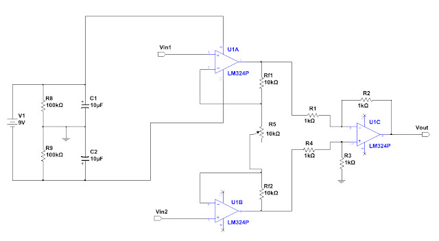
The schematic diagram of the LM324 instrumentation amplifier is shown below.

\[A = \frac{V_{out}}{V_{in2}-V_{in1}} = \frac{R_{2}}{R_{1}}(1+\frac{2 R_{f}}{R_{5}})\]
where, \(R_{f1} = R_{f2} = R_{f}\) and \(R_{2} = R_{3}\), \(R_{1} = R_{4}\)
\[A = 1+\frac{2 R_{f}}{R_{5}}\]
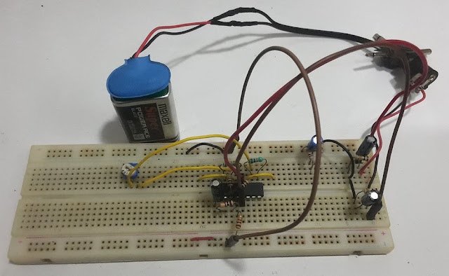
The following picture shows the LM324 instrumentation amplifier on a breadboard.

To test the LM324 instrumentation amplifier on the breadboard in real time with actual signal we will use Proteus Software . The Proteus software has speaker and microphone components which can be used to send out signal from the PC speaker and acquire signal using the microphone/line in port of the PC. The following shows how the speaker and the microphone component in Proteus electronics design Software are used in this tutorial.

In the above picture, a signal generator or function generator is connected to the speaker. The function generator can be used to output various types of signals such as sine wave, triangle wave, square wave etc. We can control the signal amplitude and frequency of the generated signal. The generated signal is then sent to the PC speaker. The signal generator control panel in proteus software is shown below.

The signal which is sent out from the PC speaker is then fed into the instrumentation amplifier on the breadboard using male to male audio jack. The output from the amplifier is then sent into the microphone/line in input of the PC. This signal is collected by the microphone component in proteus software as shown above. The output of the microphone component is connected to the oscilloscope. The output of the instrumentation amplifier can then be viewed on the oscilloscope in real time.
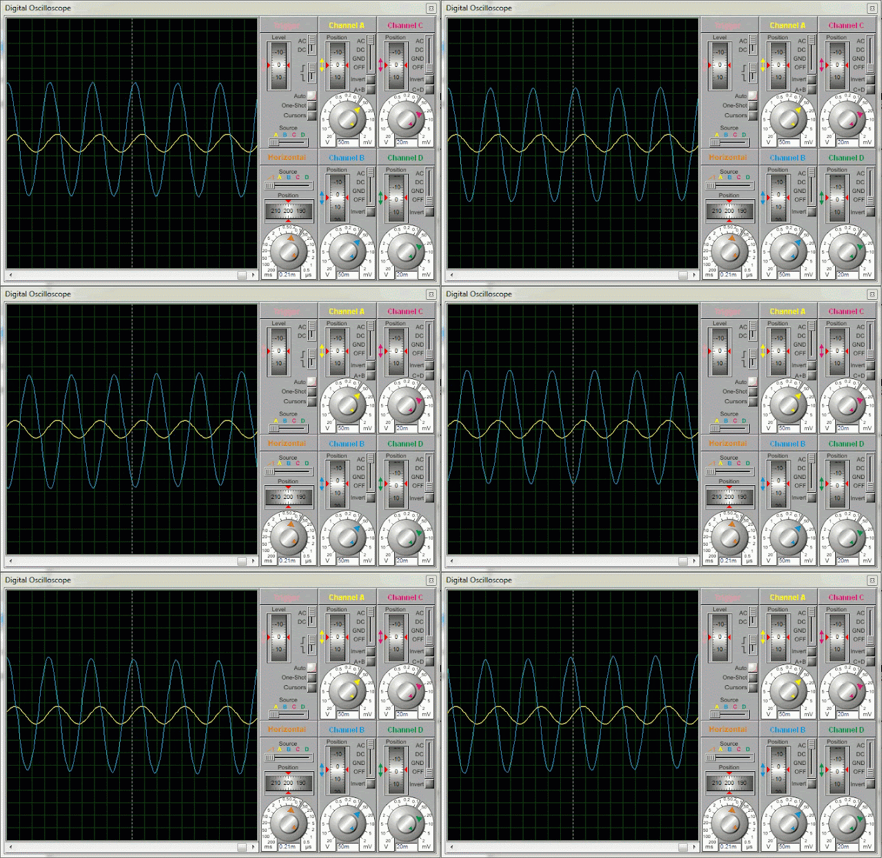
The following shows the input and output waveform on the oscilloscope obtained in real time.

How to connect the signal output from the PC speaker to the amplifier input on the breadboard using male to male audio jack and how to connect the amplifier output to the mic/line in port of PC was shown in the tutorial LM741 non-inverting amplifier with dual supply from single supply .
In this example tutorial we have used Proteus Software for testing the circuit. If you don't have Proteus Software, the instrumentation amplifier circuit above can also be tested using Matlab/Simulink based oscilloscope and spectrum analyzer as was done in the following tutorials.
- LM324 op-amp Integrator testing with matlab simulink oscilloscope
- Square wave to Triangle Wave with LM324 Op-amp
- Function generator using LM324 op-amp
Or, one can also use Labview Software based oscilloscope and function generator as was illustrated in the following tutorials.
- How to Build BJT amplifier and test with Soundcard based PC Oscilloscope
- Testing of self biased BJT amplifier on breadboard with PC oscilloscope
- Copy Link Copied

Post a Comment
Our website uses cookies to improve your experience. Learn more

IMAGES
VIDEO
COMMENTS
Lab$4:Instrumentation$ Amplifier$!!! Instrumentation!Amplifier! LAB!4:!Instrumentation!Amplifier! ELECTRICAL!ENGINEERING!43/100! INTRODUCTIONTOMICROELECTRONICCIRCUITS!
Lab 6: Instrumentation Amplifier . INTRODUCTION: A fundamental building block for electrical measurements of biological signals is an instrumentation amplifier. In this lab, you will explore the operation of instrumentation amplifiers by designing, building, and characterizing the most basic instrumentation amplifier structure.
Designing an Instrumentation Amplifier 1. Select an Op Amp. Selecting an appropriate op amp is an important part in designing an instrumentation amplifier. The instrumentation amplifier will require three op amps. Almost any op amp will work for this design. However, with circuit size in mind, this design will use the LM324.
Measurements & Electronic Instruments Laboratory Experiment Manual . Department of Electrical Engineering, I.I.T. Kharagpur . Experiment No. : 12 . INSTRUMENTATION AMPLIFIER . Objective: To study the characteristics of an Instrumentation Amplifier. Circuit diagram: The circuit diagram of a 3 Op-amp. Instrumentation Amplifier is shown in Fig-1.
Start work on design of variable-gain instrumentation amplifier before coming to the lab. Experiments: Part 1: 1. Op-Amp's Open Loop Response ... Test Circuit. Obtain an op-amp from the parts bin. The pin out is given below in Fig. 1. Fig. 1: Pin-out of UA741CN op-amp. Now using a proto-board, assemble the open loop op-amp test circuit shown ...
1. Attach the output of the Lab 6 instrumentation amplifier to the input of your cascaded bandpass filter and to Ai1 of the Elvis Board. 2. Connect the output of the bandpass filter to Ai0 of the Elvis Board. Connect the ground of the amplifier/filter circuit breadboard to Aground of the Elvis Board. 3. Open LabVIEW and open a new blank project.
of what an instrumentation amplifier is, how it operates, and how and where to use it. In addition, several dif-ferent categories of instrumentation amplifiers are addressed in this guide. IN-AMPS vs. OP AMPS: WHAT ARE THE DIFFERENCES? An instrumentation amplifier is a closed-loop gain block that has a differential input and an output that
The Amplifier Our amplifier is built around the AD624AB instrumentation amplifier chip from Analog Devices. Please take some time to look at its data sheet, found in the supplementary reading section, to understand its function. At our gain of a 1000, this amplifier gives us a CMR of 110 dB. Our amplifier design is shown in Figure 2. Build
5.3 Normal-mode and Common-mode Gain of Instrumentation Amplifier . Background To make strain gage measurements, we use the bridge circuit shown in Fig. 5.3.1. Figure 5.3.1 AD620 Instrumentation Amplifier Circuit Board Schematic. This circuit board has three notable features as follows: (a) Connections are provided for four external resistors R ...
Here instrumentation amplifier is build on breadboard using the LM324 op-amp. The instrumentation amplifier is then tested with Proteus Software . We had explained earlier what is instrumentation amplifier & types of instrumentation circuits and showed LM324 Op-Amp Instrumentation amplifier design example using ac coupling, basing and with ...